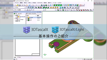
3DTascalX
More than a viewer, less than a CAD
A 3D data handling tool that uses Parasolid(R), the same software as 3D CAD, to enable viewing, measurement, and conversion.
ABOUT What is 3DTascalX?
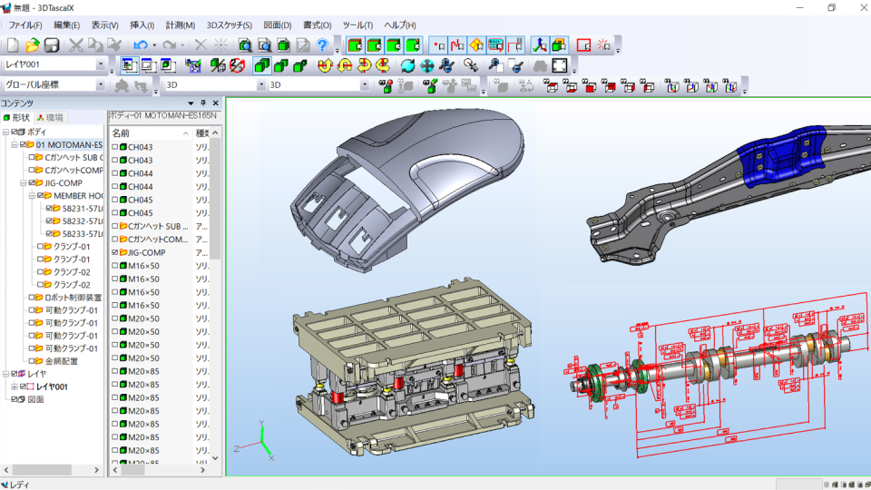
Its greatest feature is developed with the Parasolid kernel same as major 3D CAD.
Except design (modeling) functions, it has almost same functionality of CAD.
A viewer isn't enough, but don't need CAD, this software meets those requirement.
(*)Parasolid
The world's most advanced 3D geometric modeling component software.
It is used as the modeling foundation for Siemens PLM Software's NX and Solid Edge products. (From the Siemens PLM Software website)
Data Conversion
It is possible to input and output major CAD data such as CATAI, NX, Creo Parametric, SOLIDWORKS, and Inventor, as well as intermediate files such as IGES, STEP, and Parasolid. It also supports 2D data such as CATDrawing, DXF, and DWG.
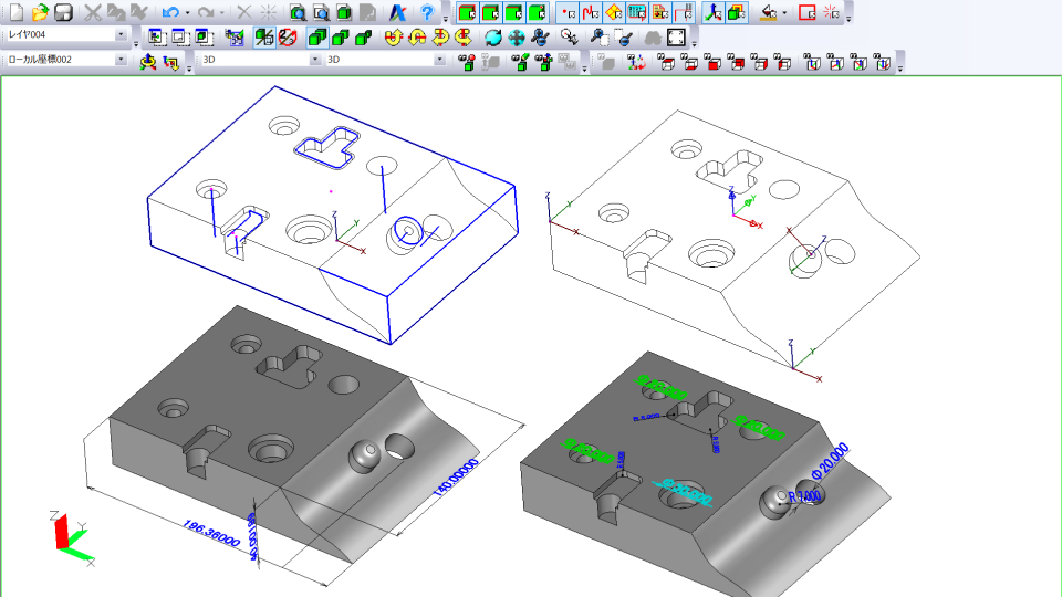
High-precision measurement and 3D sketching
In addition to measuring 3D shapes, the sketch function allows you to interpolate gaps between parts and materials by drawing intersections, midpoints, offset lines, etc. Furthermore, by setting secondary coordinates, absolute and relative values can be easily calculated.
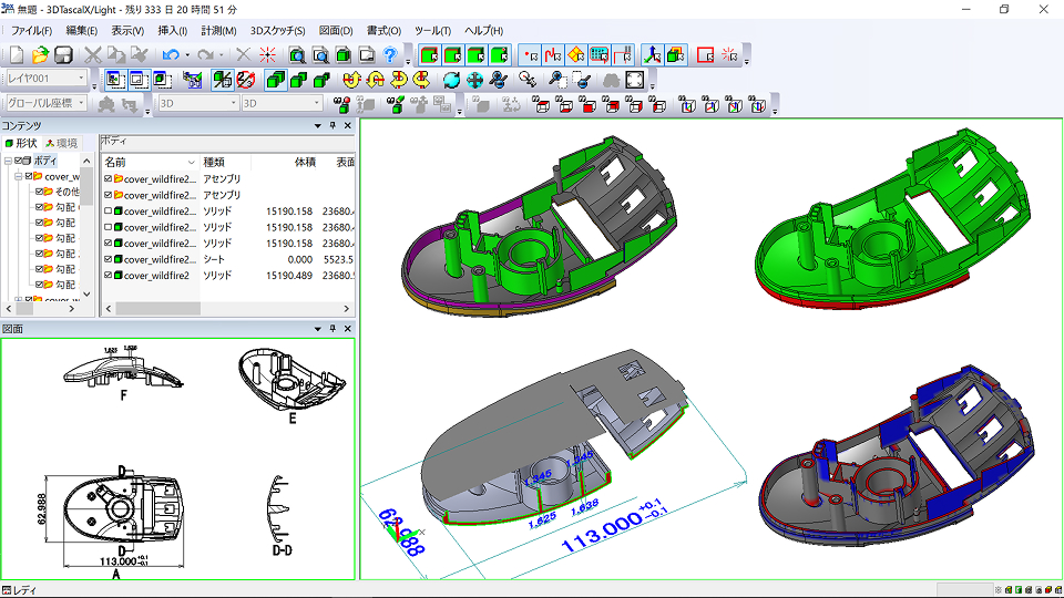
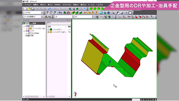
Color-coded verification function
Design changes, slope angles, thickness, undercuts, heights, holes, and fillets can be color-coded by their respective values.
VIDEO 3DTascalX Promotional Video
FEATURE Features of 3DTascalX
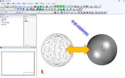

Made with Parasolid Kernel
This software is built using the same karnel as 3D CAD, enabling high-precision measurements up to 1/100,000,000 required.
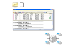
Bulk Conversion
Automatic batch conversion of data is possible through folder monitoring.
A command line interface is also available, allowing you to launch conversion from an external application.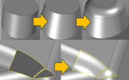
Data Editing
(Paid option)3D data can be edited. Surface removal, hole filling, fillet deletion/addition, taper addition, shrinkage, etc.
3D annotation support
It is possible to import dimensions, notes, view information, etc. added to 3D data in CAD. In addition, property information added to parts in CATIA and NX data can also be imported.
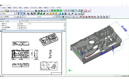
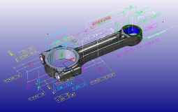
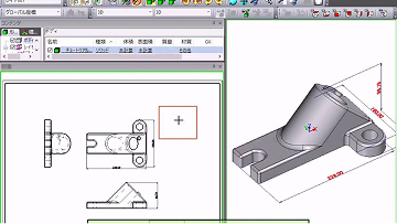
2D drawing
3D data can be easily developed into 2D drawings such as three-dimensional views and cross-sections. Furthermore, splines and ellipses can be output as approximate arcs. For assembly data, there is also a function to create drawings for each part at once.
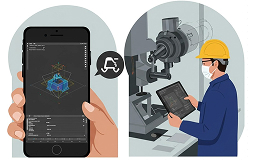
Data Sharing
(Paid option)By outputting 3D data to a dedicated free viewer or PDF, you can share the data with business partners and other departments. Data formats are available that are compatible with not only Windows, but also Android and iOS.
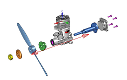
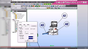
presentation
It is possible to create video presentations by breaking down assembly data and adding motion.
USE CASES Main usage scenarios

Design Department
By consolidating data conversion in 3DTascalX, CAD work doesn't need to be stopped. It also reduces running costs.

Production Engineering Department
When you don't have enough CAD licenses for drawing inspection work, or when the 3D viewer you are using doesn't have enough functionality.

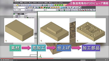
Machining Department
You can plan and consider machining before the 2D drawings are released. Even if the drawings contain missing dimensions, you can measure them yourself without having to check with the design team or your supplier, reducing wait times.

Sales Department
Easily calculate volume, surface area, mass, and maximum external dimensions. It runs smoothly on a laptop, so you can work on the go.

Inspection Department
In addition to dimensional measurement, you can also set tolerances and input actual measurements to save inspection results.
You can also set probe coordinates for 3D measuring machines.
For those who want to know more
For those who want to know more about the functions and examples of the 3DTascalX series, we have prepared videos that explain the specific usage methods and introduction effects in each business.
FUNCTIONS Function
Display function
- Shading, wire, hidden line, and edge enhancement displays
- Perspective display
- Transparency display
- Cross section display
- Viewpoint direction display
- Dynamic view movement
- Focus display
- Lighting
- Lightweighting
- Part search
- Subscreen display
- Shading, wire, hidden line, and edge enhancement displays
Measurement function
- Distance measurement
- Angle measurement
- Arc measurement
- Face diameter/radius measurement
- C chamfer measurement
- Automatic hole dimension measurement
- Line length measurement
- Volume, surface area, mass measurement
- Maximum outer dimensions
- Coordinate values
- Probe offset coordinate values
- Inspection measurement value input
- Distance measurement
3D sketch function
- Points
- Lines
- Circles
- Spline Lines
- Planes
- Projection Lines, Points
- Section Lines
- Face Intersection Lines, Center Lines, UV Lines, Line Trim, Invert, Extend, Shorten, Joint
- Area Lines
- Points
Drawing function
- Batch Drawing Output
- Projected Drawing
- Isometric Drawing
- Arrow View
- Cross-Section View
- Line Grid
- Bill of Materials
- Dimensions
- Comments
- Insert Coordinate Axis
- Approximate Arc
- Supports Scale, Elements, Line Types, and Colors
- Batch Drawing Output
Model operation function
- Solidification (IGES → Parasolid)
- Surface Separation (Solid → Sheet)
- Gap Filling
- Face Offset
- Automatic Hole Filling/Manual Face Deletion
- Sheet Hole Loop Removal
- Body Check
- Part Color Settings (Face Color Attributes Can Be Set)
- Projection Plane Creation
- Face Merging
- Fillets and Tapers
- Solidification (IGES → Parasolid)
Movement function
- Direct movement
- Mirror, translation, and rotation
- Height alignment
- Two-axis alignment
- Coordinate axis origin movement
- Direct movement
Pre-verification function
- Color-coded surface height
- Color-coded surface slope angle
- Color-coded design change areas
- Color-coded shadow surfaces
- Color-coded wall thickness
- Height, slope, and hole color table
- Part shrinkage
- Color-coded surface shape
- Color-coded surface height
Other features
- Create local coordinates
- Create comments and notes
- Create viewpoints
- Create presentations
- Create markups
- Display thumbnails
- Create local coordinates
Accessory modules
- Free viewer for exclusive use of 3DX(3DTascalX format)「3DX Reader」 2D Viewer「D-view Plus」
- 3d data batch conversion module「i2x Plus」
- Color attribute change tool「TableEditor Plus」
- License Management Application「Activation Manager」
- Free viewer for exclusive use of 3DX(3DTascalX format)「3DX Reader」 2D Viewer「D-view Plus」
SUPPORTED FORMATS Supported formats
-
Data Format Extension VER IN OUT Parasolid *.x_t
*.x_b
*.xmt_txt
*.xmt_binV9 – V37.1 Assembly
Parts
Points
WireAssembly
Parts
Points
WireSTEP *.stp
*.stepAP203
AP214Assembly
Parts
Points
WireParts
Points
WireIGES *.igs
*.igesVer5.3 Assembly
Parts
Points
WireAssembly
Parts
Points
WireSOLIDWORKS *.sldasm
*.sldprt2022 – 2026 Assembly
PartsAssembly
Parts (Software environment required)STL *.stl 


VRML *.wrl V1.0,V2.0 -
Data Format Extension VER IN OUT CATIA V5 *.CATProduct
*.CATPartIN : V5R8 – V5-6R2026
OUT : V5R16 – V5-6R2024Assembly
Part
Wire
PMI (Symbol)
Secondary CoordinatesAssembly
Parts
WireCATIA V4 *.model
*.expV4.1.9 – V4.2.4 Parts
Wires
Layer InformationParts
Wire (*.model only)NX *.prt UnigraphicsV11 – V18
Unigraphics/NX – NX2512Assembly
Part
Point
Wire
Layer Information
PMI (Symbol)Creo Parametric *.asm
*.prtPro/ENGINEER16 – Wildfire5
Creo1.0 – 12.0Assembly
Parts
Wire
Free Surface
PMI (Symbol)CFIO *.cfio
(Compressed cfio format is not supported)5R, V6 all Assembly
Part
Wire
Layer InformationJT *.jt IN : V8.1-V10.10
OUT : V9.0-V10.10Assembly
Part
PMI (Symbol)Assembly
Part
PMI (Symbol)ACIS *.sat IN : R4 – R2026.1.0
OUT : R18 – R2020.1.0Body
Point
WireBody
Point
Wire3DPDF *.pdf Assembly
Part
PMI (Symbol)Inventor *.ipt
*.iamV11 – V2026 Assembly
Parts
Point
WireSTEP *.stp
*.stepAP242 Assembly
Parts
Points
Wire
PMI (Symbol)Assembly
Parts
Points
Wire3DX ReaderDS *.3dxds Assembly
Parts
PMI (Symbol)
Wire -
Data Format Extension VER IN OUT 2DDXF *.dxf IN : R12 – 2018
OUT : R12 – 2007
(D-view Plus) 2DDWG *.dwg IN : R12 – 2018
OUT : R12 – 2007
(D-view Plus) HPGL *.hgl
*.hpgl
*.hpg
*.pgl
(D-view Plus)NAZCA5 CAD *.n5cadx -
Data Format Extension VER IN OUT CATDrawing *.CATDrawing V5R8 – V5-6R2026
(D-view Plus) -
Data Format Extension VER IN OUT JPEG *.jpg BMP *.bmp AVI *.avi CSV *.csv
- The SOLIDWORKS Assembly Feature is not supported.
- SOLIDWORKS is required on your PC to export to SOLIDWORKS.
- When exporting DXF or DWG with D-view Plus, compound elements such as dimensions will be exploded into lines, text, etc.
- The Creo Parametric interface option may require an instance accelerator file when importing assemblies.
- The JT interface option can only read JT files in XT-Brep format.
- Please view exported PDF files using the latest version of Adobe Reader.
Recommended environment
| OS (64-bit only) | Windows 11 Pro (Desktop Mode) |
|---|---|
| CPU | Intel Core i5 series or higher recommended |
| Memory | 16GB |
| Graphics | OpenGL accelerated graphics recommended *1 |
| Others | Internet connection *2 |
- *Your graphics environment may affect 3D operations. Please check the operation with the trial version beforehand.
- *You will need this when you first activate your license or when renewing maintenance support, but there is also a proxy authentication function that allows you to authenticate via an online PC.
PRICING Pricing
Main product
3DTascalX V12 Node lock license
$2,620
$550
3DTascalX V12 Floating License *1
$2,620 x QTY + $730
$550 x QTY
Annual maintenance support fee *2
CATIA V5 (R) Interface Option
$620
CATIA V5 (W) Interface Option
$1,100
CATDrawing (R) Interface Option
Node lock license$825
Floating License$1,650
CATIA V4 (RW) Interface Option
$420
NX (R) Interface Option
$420
Creo Parametric (R) Interface Option
$420
CFIO (R) Interface Option
$420
Inventor (R) Interface Option
$330
JT (R) Interface Option
$330
JT&3DPDF (W) Interface Option
$330
3DXDS (W) Interface Option
$165
STEP AP242 (RW) Interface Option
$165
ACIS (RW) Interface Option
$30
Model Modification Option
$165
Other Products
3DTascalX V12 Node lock license Installation work fee*3
Please contact your local distributor for pricing.
3DTascalX V12 Floating License Installation work fee*3
Please contact your local distributor for pricing.
3DTascalX V12 Installation & training work fee*3
Please contact your local distributor for pricing.
Precautions
- Product configuration and prices are subject to change without notice. Please note.
- This product is primarily installed via download.
- The academic version is approximately 10% of the product price. Please inquire separately.
Maintenance Support
- The first year of maintenance support is required.
- The latest version (including version upgrades) can always be downloaded from the user page.
- We will provide you with our product information as it becomes available.
- We will respond to all support inquiries regarding this product.
- You can purchase a minimum of one license. In addition to the base price, an additional fee of $730 will be charged for the first time.
- Annual maintenance support is required to use each interface option.
If you do not pay the annual maintenance support and annual usage fee, you will not be able to use the interface option. - If only the installation work is required, it will generally be handled online; if an in-person visit is required, additional travel expenses will be incurred.
Floating license installation requires that TCP/IP communication is possible between the server and client.
Contact us here for development requests or consultations.